Key Features
APRON FEEDER HAF
TECHNICAL DATA
APRON FEEDER | HAF
| Machine | Width [mm] | Length A-A [mm] | Chain Type |
| HAF 10100 | 1.000 | 10.000 | D3 |
| HAF 12100 | 1.200 | 10.000 | D3 |
| HAF 14106 | 1.400 | 10.600 | D4 |
| HAF 14133 | 1.400 | 13.300 | D5 |
| HAF 16106 | 1.600 | 10.600 | D5 |
| HAF 16133 | 1.600 | 13.300 | D5 |
| HAF 18106 | 1.800 | 10.600 | D5 |
| HAF 18116 | 1.800 | 11.600 | D7 |
| HAF 20115 | 2.000 | 11.500 | D4 |
| HAF 20116 | 2.000 | 11.600 | D7 |
| HAF 22116 | 2.200 | 11.600 | D7 |
| HAF 25115 | 2.500 | 11.500 | D8 |
| HAF 25142 | 2.500 | 11.420 | D8 |
PRODUCT DESCRIPTION
HAZEMAG’s HAF Apron Feeders are used for feed hopper discharging in primary crushing plants, and as a loading or discharging conveyor in, for example, the cement and raw material industry. HAZEMAG Apron Feeders provide capacities of up to 4,000 t/h with piece sizes up to 3m3.
When selecting a suitable hopper discharge unit, it is very important to ensure that material is conveyed to the downstream machine at a variable conveying speed, under varying load conditions.
The hopper geometry must match the hopper discharge unit, and the hopper discharge unit, in turn, has to match the downstream unit.
Since 1981, more than 178 HAZEMAG Apron Feeders have been put into operation world-wide.
The Apron Feeder is used to remove the material from a feed hopper or as an additional material conveyor unit. The Apron Feeder ensures an approximately equal material feed rate. The conveyor speed and thus the output can be set via a frequency converter on the system.
The Framework consists of two heavy main beams which are connected together via several cross beams. The track rollers and the sliding rails are mounted on the cross beams supports and guide the tractor chain. The covers are also mounted on the framework and serve as an isolating safeguard against moving machine parts.
The tensioning station and drive shaft bearings are connected to the heavy main beams. The tension shaft bearings are guided by the tensioning station.
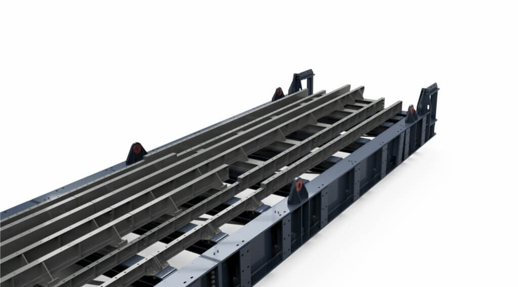
The Tractor Chain consists of crawler tracks which are interconnected to form a strand.
The apron feeder has always two chain strands.
An apron pan is bolted to each link of the tractor chain. Every second pan is equipped with a carrier; this secures a perfect material transport.
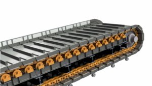
The upper run of the tractor chain runs on track rollers. In the hopper area the track rollers are mounted on heavy rubber blocks, which protect the construction and increase the machine lifetime, because they absorb the impacts from of the hopper feeding.
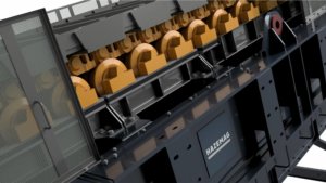
The apron´s specific contour prevents largely the entering of material into the apron feeder. Thus, additional wear at the tractor chain will be minimized.
One chain drive sprocket is mounted for each tractor chain strand on the drive and tensioning shaft. The chain drive sprocket on the drive shaft transfers the rotational motion of the drive to the tractor chain. The chain drive sprocket on the tensioning shaft serves as a chain guide.
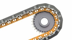
In-between the two chain strands are sliding rails arranged, which are mounted onto the framework. They prevent a possible bending from the hopper feeding and thus increase the lifetime of the apron pans.
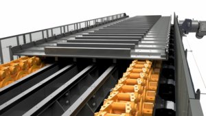
Mounted directly under the Apron Feeder, the Spillage Conveyor HCC is a chain conveyor used to collect any remnants of conveyed material which, having adhered to the Apron Feeder pans, drops off on the return side. The Apron Feeder and the Spillage Conveyor work in tandem, but are operated independently.
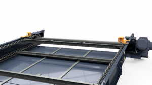
Spillage Conveyor comprises:
- Drive shaft assembly with two cast sprockets and pillow block bearings.
- Power transmission via geared motor.
- Two sets of round link steel chain with scraper bars bolted at equal intervals.
- Take-up shaft assembly with two cast sprockets and pillow block bearings.
- Pre-tensioning of chains by tension spindles with springs.
- The space between drive and tension shaft assembly is connected by bolted flanges.
Monitoring
The operation of the Spillage Conveyor is continuously monitored by a rotation detector at the tail shaft.
- PBRK


